Chapter 3: Sensors and Perception
Chapter Overview
Welcome to the world of robotic senses! Just as humans rely on sight, hearing, and touch to navigate and interact with their environment, robots depend on an array of sensors to perceive the world around them. This chapter is your guide to the fundamental building blocks of robotic perception. We will explore the "eyes," "ears," and "inner ear" of a humanoid robot, focusing on the three most critical sensing modalities in modern robotics:
- Cameras: The robot's primary visual sensors, providing rich, detailed information about the environment.
- LiDAR: A powerful technology that uses light to measure distances with high precision, enabling robots to "see" in 3D.
- IMUs (Inertial Measurement Units): The key to a robot's sense of balance and orientation.
We will delve into the operating principles of each sensor, discuss their strengths and weaknesses, and examine their canonical use cases in humanoid robotics. Finally, we'll introduce the concept of sensor fusion, the art of combining data from multiple sensors to create a perception system that is more robust and reliable than the sum of its parts. By the end of this chapter, you will have a solid understanding of how robots perceive their world, paving the way for more advanced topics in navigation, manipulation, and artificial intelligence.
The Senses of a Robot
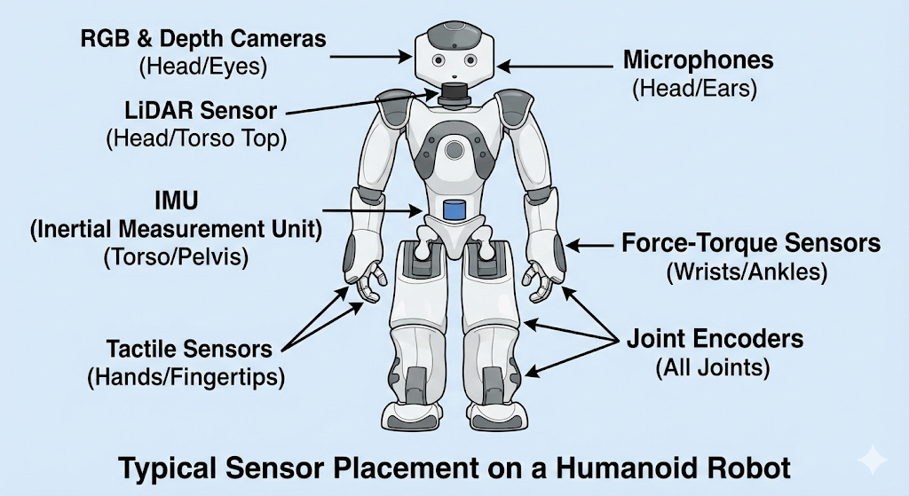
Robotic sensors can be broadly categorized into two main types, based on what they measure: the external world or the robot's own internal state.
Exteroceptive Sensors: Sensing the World
Exteroceptive sensors are those that gather information about the robot's external environment. They are the robot's equivalent of our five senses, allowing it to see, hear, and feel the world around it. These sensors are crucial for tasks like navigation, obstacle avoidance, and object manipulation.
Common exteroceptive sensors include:
- Cameras: Capture images and video, providing rich visual data.
- LiDAR: Measure distance to objects by illuminating them with laser light.
- Microphones: Detect sound.
- Tactile Sensors: Provide a sense of touch, often used in robotic hands.
Proprioceptive Sensors: Sensing the Self
Proprioceptive sensors, on the other hand, monitor the internal state of the robot itself. The term "proprioception" comes from the Latin words proprius ("one's own") and capio ("to take or grasp"), and it refers to the sense of self-movement and body position. These sensors are vital for balance, stability, and coordinated movement.
Common proprioceptive sensors include:
- Inertial Measurement Units (IMUs): Measure the robot's orientation, angular velocity, and linear acceleration, much like the human inner ear.
- Joint Encoders: Measure the position and velocity of the robot's joints, providing feedback on limb placement and movement.
- Force-Torque Sensors: Measure forces and torques exerted on different parts of the robot, which is essential for tasks requiring a delicate touch.
In this chapter, we will focus primarily on the key exteroceptive sensors (Cameras and LiDAR) and the most important proprioceptive sensor for a humanoid robot's balance (the IMU). Understanding the interplay between these different sensing modalities is fundamental to building intelligent and capable robots.
Cameras: The Robot's Eyes
Cameras are arguably the most important sensors in robotics, providing a rich and intuitive source of information about the world. They are inexpensive, ubiquitous, and the data they produce—images—is conceptually similar to how humans perceive their environment. In this section, we'll explore the two main types of cameras used in robotics: RGB cameras and depth cameras.
RGB Cameras: Seeing in Color
An RGB (Red, Green, Blue) camera works much like a digital camera or the human eye. It captures light from the environment through a lens and focuses it onto an image sensor. This sensor is a grid of millions of tiny light-sensitive elements that measure the intensity and color of the light at each point, producing a two-dimensional color image.
- Operating Principle: Based on the pinhole camera model, where light from the scene passes through a tiny aperture and is projected onto a sensor plane.
- Output: A 2D grid of pixels, where each pixel has a color value typically represented by three numbers (R, G, B).
- Use Cases: Object recognition, facial identification, reading text, tracking moving objects, and visual SLAM (vSLAM), where the robot builds a map of its environment using camera images.
Depth Cameras: Seeing in 3D
While RGB cameras provide a wealth of information about what the world looks like, they don't directly tell the robot how far away things are. This is where depth cameras come in. These specialized sensors create an image where the value of each pixel represents its distance from the camera, effectively allowing the robot to see in three dimensions.
There are two primary technologies for depth cameras:
- Time of Flight (ToF): The camera emits a pulse of infrared light and measures the time it takes for the light to bounce off an object and return. Since the speed of light is constant, this "time of flight" can be directly converted into a distance measurement.
- Structured Light: The camera projects a known pattern of infrared light (e.g., a grid of dots) onto the scene. It then observes how this pattern is distorted by the objects it hits. By analyzing the deformation of the pattern, it can calculate the distance to every point in the scene.
- Operating Principle: Measure distance on a per-pixel basis using either Time of Flight or Structured Light techniques.
- Output: A 2D depth map or a 3D point cloud, where each point has an (x, y, z) coordinate.
- Use Cases: 3D reconstruction of environments, grasp planning for object manipulation, and close-range obstacle avoidance.
Strengths and Weaknesses
| Strengths | Weaknesses |
|---|---|
| High Resolution & Rich Data: Provide detailed | Sensitive to Lighting: Performance degrades in low light or |
| color and texture information. | very bright light. |
| Inexpensive: Standard RGB cameras are a low-cost | 2D Information Only (RGB): A standard RGB camera cannot |
| commodity component. | directly measure depth. |
| Passive (RGB): They don't emit their own energy, | Computationally Intensive: Processing high-resolution |
| making them safe and power-efficient. | images can require significant computational power. |
| Limited Range (Depth): Most depth cameras are effective | |
| only at short to medium ranges. |
LiDAR: Seeing with Light
Where cameras provide a dense, colorful picture of the world, LiDAR (Light Detection and Ranging) provides something arguably more fundamental for robotics: precise, accurate measurements of distance. LiDAR is an active sensor that works by illuminating the environment with laser beams and measuring the reflections.
- Operating Principle: The core principle behind most LiDAR sensors is Time of Flight (ToF). The sensor emits a pulse of laser light and starts a timer. When the light reflects off an object and returns to the sensor, the timer is stopped. By multiplying the elapsed time by the speed of light and dividing by two (for the round trip), the sensor can calculate the distance to the object with very high accuracy.
- Output: The raw output of a LiDAR sensor is a collection of distance measurements, which are typically processed into a point cloud. A point cloud is a set of data points in 3D space, representing the external surfaces of objects in the scene.
- Use Cases: LiDAR is the sensor of choice for Simultaneous Localization and Mapping (SLAM), where a robot builds a map of an unknown environment while simultaneously keeping track of its own position within that map. It is also heavily used for obstacle detection, navigation, and environmental modeling.
2D vs. 3D LiDAR
LiDAR sensors are commonly found in two configurations:
- 2D LiDAR: These sensors typically have a single laser emitter/receiver pair that spins at a high speed, scanning a single horizontal plane around the robot. The result is a 2D "slice" of the world, which is extremely useful for navigation and obstacle avoidance in flat environments.
- 3D LiDAR: To capture a full three-dimensional view, 3D LiDARs use multiple laser beams (often stacked vertically) or a more complex mirror assembly to scan the environment in multiple planes. This produces a dense 3D point cloud, providing a much richer and more complete representation of the robot's surroundings.
Strengths and Weaknesses
| Strengths | Weaknesses |
|---|---|
| High Accuracy: Provides precise distance | No Color Information: LiDAR only measures distance, not |
| measurements. | the color or texture of objects. |
| Works in Any Lighting: As an active sensor, it | Expensive: High-end 3D LiDAR units can be very costly, |
| performs equally well in bright daylight or complete | though prices are decreasing. |
| darkness. | Struggles with Certain Surfaces: Can have difficulty with |
| Long Range: Can often measure distances much | transparent (glass) or highly reflective (mirrors) surfaces. |
| further than depth cameras. |
IMUs: The Sense of Balance
While cameras and LiDAR sense the external world, the Inertial Measurement Unit (IMU) senses the robot's own motion. As a proprioceptive sensor, it is the robotic equivalent of the human inner ear, providing the crucial data needed for a humanoid robot to balance, stabilize itself, and understand its orientation in space.
- Operating Principle: An IMU is a compact electronic device that bundles multiple sensors together. The two most important components are:
- Accelerometer: Measures linear acceleration (the rate of change of velocity) along three axes (x, y, z). By measuring the constant acceleration of gravity, an accelerometer can also determine the sensor's tilt with respect to the ground.
- Gyroscope: Measures angular velocity (the rate of rotation) around three axes. By integrating these rotational velocities over time, the IMU can track how its orientation is changing.
- Output: An IMU typically outputs its raw measurements (linear acceleration and angular velocity) as well as a fused orientation estimate, often represented as a quaternion or Euler angles (roll, pitch, yaw).
- Use Cases: The primary use case for an IMU in a humanoid robot is state estimation, particularly for maintaining balance. It's the key sensor that tells the robot if it's falling over and what control actions it needs to take to stay upright. It is also critical for dead reckoning, a method of estimating position based on a previously known position and advancing it based on measured speed and direction over time.
The Challenge of Drift
The single biggest challenge with IMUs is drift. Because the IMU calculates orientation by integrating gyroscope measurements over time, any small, persistent error (or bias) in the gyroscope readings will accumulate, leading to a gradually increasing error in the orientation estimate. This is like a car with a slightly misaligned steering wheel; over a long distance, it will drift significantly from a straight line. Because of drift, IMUs are excellent for measuring short-term changes in motion but cannot be relied upon for accurate long-term position and orientation tracking without help from other sensors.
Strengths and Weaknesses
| Strengths | Weaknesses |
|---|---|
| High-Frequency Data: Provide very fast updates | Drift: Suffers from accumulating errors over time, making |
| about the robot's motion. | it unreliable for long-term localization by itself. |
| Small and Inexpensive: IMUs are small, low-power, | Sensitive to Noise: The sensor readings can be "noisy," |
| and relatively cheap. | affected by vibrations and sudden movements. |
| Self-Contained: Requires no external features or | |
| infrastructure to operate. |
From Raw Data to Perception
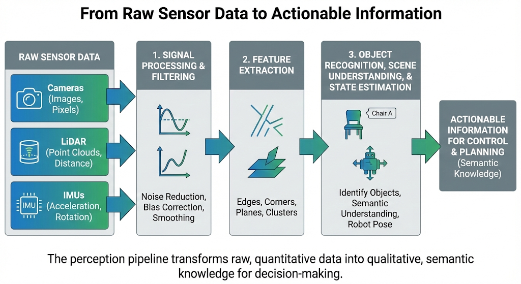
The sensors we've discussed provide a firehose of raw data: a grid of color values from a camera, a cloud of 3D points from a LiDAR, and a stream of acceleration and rotation values from an IMU. This raw data, on its own, is not very useful. A robot cannot make decisions based on an array of numbers; it needs to interpret this data to understand its environment and its own state.
This process of turning low-level sensor data into high-level, actionable information is the core of perception. It is often conceptualized as a pipeline or a "stack" of processing steps:
-
Signal Processing and Filtering: The first step is to clean up the raw data. Sensor readings are inevitably noisy. Algorithms are used to filter out random fluctuations and correct for known sensor biases. For an IMU, this might involve smoothing out jerky readings; for a camera, it could mean adjusting for changing light conditions.
-
Feature Extraction: Once the data is cleaned, the next step is to extract salient features. A "feature" is a piece of information from the data that is distinctive and relevant for a specific task.
- For a camera image, features might be edges, corners, or patches of a certain color.
- For a LiDAR point cloud, features could be planar surfaces (like walls and floors) or clusters of points that might represent an object.
-
Object Recognition, Scene Understanding, and State Estimation: This is the highest level of the perception stack, where the extracted features are interpreted to produce a semantic understanding of the world.
- Using features from a camera and LiDAR, an object recognition algorithm might identify a cluster of points and pixels as a "chair" or a "person."
- Using the filtered data from an IMU, a state estimation algorithm will calculate the robot's current orientation and velocity.
In essence, the perception pipeline transforms a flood of raw, quantitative data into qualitative, semantic knowledge that the robot's "brain" (its decision-making and planning algorithms) can use to achieve its goals. Raw data tells the robot what the sensor sees; perception tells the robot what is there. This semantic knowledge is the crucial input that feeds the robot's control loop, allowing it to make intelligent decisions and act upon them.
An Introduction to Sensor Fusion
As we've seen, every sensor has its own set of strengths and weaknesses. Cameras provide rich color but are sensitive to light. LiDAR provides accurate depth but is expensive and colorless. IMUs provide fast motion data but suffer from drift. If a robot were to rely on just one of these sensors, it would inherit all of its limitations, making it brittle and unreliable.
The solution is sensor fusion: the process of combining data from multiple different sensors to produce a more accurate, more complete, and more robust understanding of the world than any single sensor could provide on its own. The goal is to create a system where the strengths of one sensor compensate for the weaknesses of another.
This introductory chapter focuses on the "why" of sensor fusion, not the complex mathematical "how" (which often involves sophisticated algorithms like Kalman filters). Consider the following examples:
-
Compensating for Weaknesses: A camera is excellent for recognizing a pedestrian, but it struggles to do so in the dark. A LiDAR can easily detect an object's presence and distance in the dark but cannot tell that it's a person. By fusing the data from both, a robot can reliably detect and identify the pedestrian in almost any lighting condition. The LiDAR confirms something is there, and the camera, when it can see, confirms what it is.
-
Correcting for Errors: An IMU is great at tracking orientation over short time scales, but it drifts over long periods. A GPS receiver (another type of sensor) provides a globally accurate position but is only updated about once per second and can be noisy. By fusing the high-frequency data from the IMU with the low-frequency, globally accurate data from the GPS, a robot can get a location estimate that is both smooth and accurate over the long term.
The core idea is that by intelligently combining different and complementary sources of information, the robot's perception system becomes more than the sum of its parts. It becomes a more resilient and reliable foundation upon which to build intelligent behaviors.
Summary and Next Steps
In this chapter, we have taken our first steps into the world of robotic perception. We have learned to distinguish between exteroceptive sensors that perceive the world and proprioceptive sensors that perceive the robot's own state. We explored the operating principles, strengths, and weaknesses of the three most critical sensors in humanoid robotics:
- Cameras, which provide rich, colorful images of the world.
- LiDAR, which delivers precise and accurate 3D distance measurements.
- IMUs, which give the robot its essential sense of balance and orientation.
We also introduced the fundamental concept of sensor fusion, emphasizing that a robust perception system is built by combining the strengths of multiple, complementary sensors to overcome their individual weaknesses.
Now that you have a foundational understanding of what a robot senses, you are ready to learn about the software framework that allows us to process, interpret, and act on this data. In the next chapter, we will dive into the Robot Operating System (ROS 2), the open-source backbone for much of modern robotics research and development. You will learn how the data from these sensors is represented and communicated within a ROS 2 system, setting the stage for building your own robotic applications.
Practice & Reflection
-
Scenario Analysis: Imagine you are designing a robot for each of the following tasks. Which sensor (Camera, LiDAR, or IMU) would you choose as the primary sensor, and why?
- A vacuum cleaning robot that needs to navigate a cluttered apartment.
- A delivery drone that needs to fly stable and level.
- A security robot designed to recognize authorized personnel.
-
Conceptual Distinction: In your own words, what is the key difference between a proprioceptive and an exteroceptive sensor? Why are both types essential for a humanoid robot?
-
The Fusion Question: A self-driving car already has a high-end 3D LiDAR for navigation and obstacle avoidance. Why would its designers also include multiple cameras in its sensor suite? What specific capabilities do the cameras provide that the LiDAR cannot?
-
The Drift Problem: If an IMU's drift is unavoidable, why is it still considered an essential sensor for a humanoid robot? What kind of information does it provide that is difficult to get from other sensors?