Chapter 2: Humanoid Robotics Overview
Chapter Overview
Welcome to the fascinating world of humanoid robotics! This chapter provides a foundational, system-level understanding of how a humanoid robot works. We will explore the intricate web of hardware and software that allows a robot to perceive, think, and act in the real world.
Our learning objectives for this chapter are to:
- Understand the core subsystems that make up a humanoid robot.
- Visualize the layered architecture that organizes these subsystems.
- Grasp the concept of a "system of systems" and why it's crucial for complex robots.
- Follow the end-to-end data flow for a simple robotic task.
By the end of this chapter, you will have a clear mental model of a humanoid's architecture, preparing you for deeper dives into specific components in the chapters to come.
What is a Humanoid Robot?
A humanoid robot is a robot with its body shape built to resemble the human body. This design can be for functional purposes, such as interacting with human tools and environments, for experimental purposes, such as the study of bipedal locomotion, or for other purposes.
While the term "robot" covers a vast range of machines, humanoids represent a specific and challenging sub-field. Their human-like form imposes unique constraints but also offers unique capabilities. Let's compare them to other common robot types:
| Feature | Humanoid Robot | Industrial Arm | Mobile Rover |
|---|---|---|---|
| Mobility | Bipedal walking/running | Fixed in place | Wheeled or tracked |
| Workspace | Unstructured, human environments | Highly structured, predictable | Semi-structured, outdoor/indoor |
| Interaction | General-purpose, human-like | Repetitive, high-precision tasks | Navigation and sensing |
| Complexity | Very High (balance, navigation, manipulation) | High (precision, speed) | Medium (navigation, autonomy) |
Core Subsystems
A humanoid robot is a "system of systems." It's not one monolithic entity, but a collection of specialized subsystems working in harmony. Let's break down the five most critical ones.
1. Perception Subsystem
- Purpose: To gather information about the robot's internal state and its external environment. This is the robot's "senses."
- Key Components:
- Vision: Cameras (RGB, stereo, depth) to see the world.
- Proprioception: Joint encoders, Inertial Measurement Units (IMUs) to feel its own body's position and orientation.
- Exteroception: LiDAR, sonar, and force/torque sensors to sense the environment and physical contact.
- Example: An IMU reports that the robot is tilting, while a camera sees an obstacle.
2. Computation Subsystem
- Purpose: To process sensor data, run algorithms, and make decisions. This is the robot's "brain."
- Key Components:
- Onboard Computers: High-performance computers (like NVIDIA Jetson or Intel NUCs) for real-time processing.
- Specialized Hardware: FPGAs or TPUs for accelerating AI and vision algorithms.
- Networking: Ethernet, Wi-Fi for communication between components and with operators.
- Example: The main computer fuses data from the IMU and camera to determine the robot is both tilting and near an obstacle, deciding to take a step back.
3. Control Subsystem
- Purpose: To translate high-level decisions into low-level commands for the motors. This is the robot's "nervous system."
- Key Components:
- High-Level Control: Path planners, behavior trees that decide what to do (e.g., "walk to the door").
- Mid-Level Control: Trajectory generators that create smooth paths for the limbs.
- Low-Level Control: Motor controllers (e.g., PID controllers) that ensure the motors execute the desired trajectories accurately.
- Example: A trajectory generator calculates the precise angles and velocities for the leg joints to execute a "step back" motion.
4. Actuation Subsystem
- Purpose: To execute physical movement. This is the robot's "muscles."
- Key Components:
- Actuators: Electric motors (e.g., servo, stepper, brushless DC) that create motion.
- Drivetrain: Gears, belts, and linkages that transmit power from the motors to the joints.
- Joints: The mechanical parts that allow the robot to bend and rotate.
- Example: The leg motors receive commands from the controller and spin with the precise timing and torque needed to move the robot's leg.
5. Power and Safety Subsystem
- Purpose: To provide electrical energy to all components and ensure the robot operates safely.
- Key Components:
- Batteries: High-capacity Lithium-ion battery packs.
- Power Distribution Board (PDB): Regulates and distributes voltage to different components.
- Emergency Stops (E-stops): Physical buttons that can instantly cut power to the actuators in an emergency.
- Monitoring Circuits: Hardware that monitors temperature, current, and voltage to prevent damage.
- Example: The PDB provides stable 24V power to the leg motors while also supplying 5V to the onboard computer. An operator can hit the E-stop if the robot behaves unexpectedly.
The Layered Architecture
To manage this complexity, engineers often use a layered architecture. This approach organizes the software and hardware into a stack of distinct layers, where each layer has a specific responsibility and communicates with the layers directly above and below it. This promotes modularity and makes the system easier to design, debug, and upgrade.
Here is a common architectural model for a humanoid robot:
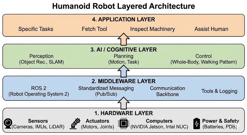
Layer 1: Hardware Layer
This is the physical foundation of the robot. It includes all the components we discussed in the "Core Subsystems" section: sensors (cameras, IMUs), actuators (motors), the mechanical frame, computers, and power systems.
Layer 2: Middleware Layer
This is the software communication backbone. It allows different software components to exchange information without needing to know the low-level details of how they are implemented or where they are running. This is where ROS 2 (Robot Operating System 2) fits in. It provides standardized messaging, data serialization, and tools for building a distributed robotics system.
Layer 3: AI / Cognitive Layer
This layer contains the intelligence of the robot. It's where the "thinking" happens. This includes algorithms for:
- Perception: Interpreting sensor data to build a model of the world (e.g., object recognition, SLAM).
- Planning: Making decisions about what to do next (e.g., motion planning, task planning).
- Control: Generating the commands to execute the plan (e.g., whole-body control, walking pattern generation).
Layer 4: Application Layer
This is the top-level layer that defines the robot's specific purpose or tasks. It uses the capabilities provided by the lower layers to accomplish a goal. For example, an application could be:
- "Fetch a specific tool from a toolbox."
- "Inspect a piece of machinery and report any anomalies."
- "Assist a person in a warehouse."
The Role of Middleware (ROS 2)
Imagine trying to build a complex software application where every component is tightly coupled. The team working on the camera driver needs to know the exact data format expected by the team working on the object recognition algorithm. If one team changes its code, the other team's code breaks. This is inefficient and error-prone.
This is the problem that middleware solves.
Middleware acts as a "software bus," a shared communication pathway that allows independent software components (which we will soon call nodes) to communicate without being directly connected. It provides a standardized way to send and receive data, insulating developers from the underlying complexities of the network and data serialization.
Why Middleware is Essential
- Decoupling: The most important benefit. A perception node can publish camera images without knowing or caring which other nodes are using them. A control node can subscribe to those images without needing to know anything about the camera driver. You can add, remove, or upgrade components with minimal impact on the rest of the system.
- Abstraction: Middleware hides the low-level details of inter-process communication. You don't need to write custom networking code to send data from one computer to another.
- Tooling: Mature middleware solutions come with a rich ecosystem of tools for debugging, visualization, and data logging. This dramatically speeds up development and troubleshooting.
ROS 2: The Middleware for Robotics
ROS 2 (Robot Operating System 2) is the most popular open-source middleware for robotics. It is explicitly designed to meet the challenges of building complex, distributed, real-time robot applications. It provides:
- A standardized, publish-subscribe messaging system.
- A rich library of drivers and algorithms.
- A powerful set of development and debugging tools.
Throughout this book, we will be using ROS 2 as the glue that holds our humanoid robot's software architecture together. It sits squarely in the Middleware Layer of our architecture, enabling all the other layers to function as a cohesive whole.
End-to-End Data Flow: A Simple Example
Let's trace the flow of data through the system for a simple task: "See a ball and pick it up." This illustrates how the layers and subsystems work together in a classic sense-plan-act cycle.
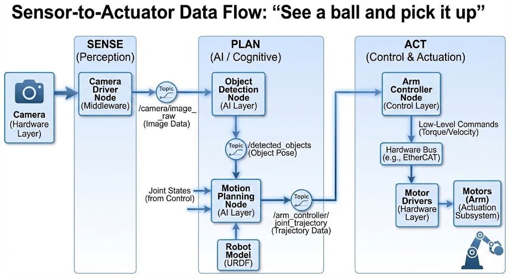
-
Sense (Perception)
- The robot's head-mounted camera (Hardware Layer) captures a continuous stream of images.
- A camera driver node (Middleware Layer) running on a computation unit publishes these images to a ROS 2 topic called
/camera/image_raw.
-
Plan (AI / Cognitive)
- An object detection node (AI Layer) subscribes to the
/camera/image_rawtopic. It processes the images and identifies a round, red object at a specific location in the robot's field of view. It publishes this finding to a/detected_objectstopic. - A motion planning node (AI Layer) subscribes to
/detected_objects. When it sees the ball, it accesses the robot's current joint states (also published to a topic by the control system) and the robot's 3D model (URDF, which we'll learn about later). - It computes a valid trajectory for the arm to move from its current position to the ball's location without colliding with itself or the environment.
- This plan, a sequence of joint angles over time, is published to a
/arm_controller/joint_trajectorytopic.
- An object detection node (AI Layer) subscribes to the
-
Act (Control & Actuation)
- The arm controller node (Control Layer) subscribes to
/arm_controller/joint_trajectory. - It translates the high-level trajectory into low-level torque or velocity commands for each of the arm's motors.
- These commands are sent over a hardware bus (e.g., EtherCAT or CAN bus) to the motor drivers (Hardware Layer).
- The motors (Actuation Subsystem) execute the commands, and the arm moves to grasp the ball.
- The arm controller node (Control Layer) subscribes to
This constant feedback is what allows the robot to react to a dynamic world.
Architectural Design Principles
Good architectural design is guided by principles that help manage complexity and create robust, maintainable systems.
1. Modularity
Modularity is the practice of designing a system as a set of independent, interchangeable modules. Think of it like building with LEGOs. Each brick (a software module or hardware component) has a standard interface that allows it to connect with other bricks.
- Analogy: You can easily swap a 2x2 red brick for a 2x2 blue brick without affecting the rest of your LEGO creation.
- In Robotics: Using ROS 2, you can replace a specific camera driver with a new one, and as long as the new driver publishes images in the same standard format, the rest of the system doesn't need to change.
2. Scalability
A scalable system can handle growth. In robotics, this can mean adding more sensors, more complex algorithms, or even more computers to distribute the processing load.
- Analogy: A well-designed website can handle a surge in traffic by adding more servers.
- In Robotics: A ROS 2 system can be scaled from running on a single laptop to being distributed across multiple onboard computers, allowing you to add more demanding perception and AI capabilities over time.
3. Fault Isolation
In a complex system, things will inevitably go wrong. A software bug might cause a node to crash. Fault isolation ensures that the failure of one component does not cascade and bring down the entire system.
- Analogy: On a modern ship, the hull is divided into watertight compartments. If one compartment floods, the bulkheads prevent the entire ship from sinking.
- In Robotics: If your object detection node crashes, the rest of the system (like the walking controller) can continue to function, allowing the robot to remain stable and safely report the failure. ROS 2's distributed, node-based architecture naturally supports this principle.
Summary and Next Steps
In this chapter, we have taken a high-level tour of humanoid robot architecture. We've seen how a complex robot is a "system of systems," composed of perception, computation, control, actuation, and power subsystems. We introduced a layered architecture that helps manage this complexity, and we traced the flow of data through this system for a simple task.
Most importantly, we've positioned ROS 2 as the critical middleware that enables these disparate components to communicate and collaborate effectively.
You now have the big picture. In the next chapter, we will begin our deep dive into the ROS 2 ecosystem, starting with its fundamental concepts: Nodes, Topics, Services, and Actions.
Practice & Reflection
- Sketch the Architecture: On a whiteboard or piece of paper, try to recreate the layered architecture diagram from this chapter without looking. Label the four main layers and list two key functions or components for each.
- Trace a Different Task: Consider the task "walk forward until an obstacle is 1 meter away, then stop." Trace the data flow for this task through the sense-plan-act cycle. What sensor is the primary input? What information would the planning node need? What would the control node command?
- Modularity in Action: Imagine you want to upgrade your robot's simple camera to a high-resolution 3D LiDAR sensor. If the system is modular, what is the only software component that you should need to change? Why?
- Fault Isolation Scenario: The motor controller for the left knee joint fails and stops sending data. In a well-designed system, what should happen? How would the rest of the robot know about the failure? What is a safe response?